

Description
Product Length/Depth: 103 mm
Product height: 83 mm
Product width: 23
Product weight: 0.11 Kg
Certifications: Standard IEC/EN 61812
CSA-22.2 No. 14
CE
CSA File No.: 012528
VDE 0435
CSA Class No.: 3211-03
UL Category Control No.: NKCR
UL 508
IEC/EN 61812-1
IEC/EN 60947-5-1
IEC/EN 61000-4-2
IEC/EN 61000-4-3
UL File No.: E29184
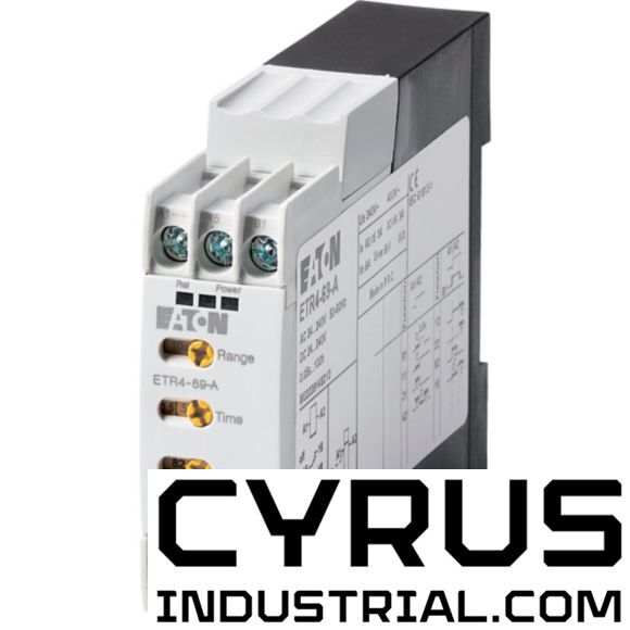
Product Tradename: ETR4
Product Type: Timing relay
Product Sub Type: None
Catalog Notes: Making and breaking conditions to DC13, time constant as stated
When supplied directly from mains or transformer > 1000 VA
Features & Functions
Electric connection type: Screw connection
Functions:
Flashing, pulse initiating: On- and Off-delayed
Pulse generating: Adjustable timing function
Outputs, reversible delayed/undelayed: Off-delayed
Pulse forming: Delay on de-energization: Multi-functional
Fleeting contact on energization: Clock function, starting with pause, variable
Clock function, starting with pulse, variable: On-delayed
Delay-on energization: Flashing, starting with pulse, fixed time
Fleeting contact on de-energization: Flashing, starting with pause, fixed time Pulse shaping
General information
Degree of protection: IP20
Terminals: IP20
Lifespan, mechanical:
30,000,000 Operations (DC operated)
30,000,000 Operations (AC operated)
Mounting position: As required
Number of contacts (change-over contacts): 1
Overvoltage category: III
Pollution degree: 2
Product category: ETR4 timing relays
Rated impulse withstand voltage (Uimp):
4000 V AC
6000 V AC
Shock resistance:
4 g, Make contact, Mechanical, according to IEC/EN 60068-2-27, Half-sinusoidal shock 20 ms
Suitable for: DIN rail (top hat rail) mounting
Terminal capacity:
1 x (0.5 - 2.5) mm², flexible with ferrule
1 x (20 - 14) AWG, solid or stranded
2 x (0.5 - 1.5) mm², flexible with ferrule
1 x (0.5 - 2.5) mm², solid
2 x (0.5 - 1.5) mm², solid
Time range - min: 0.05 s
Time range - max: 360000 s
Type: Timer relay
Voltage type: AC/DC
Climatic environmental conditions
Ambient operating temperature - min: -25 °C
Ambient operating temperature - max: 60 °C
Ambient operating temperature (enclosed) - min: -25 °C
Ambient operating temperature (enclosed) - max: 45 °C
Ambient storage temperature - min: -45 °C
Ambient storage temperature - max: 85 °C
Climatic proofing: Damp heat, constant, to IEC 60068-2-78
Damp heat, cyclic, to IEC 60068-2-30
Electro magnetic compatibility: Air discharge 8 kV
Burst impulse: 2 kV, Supply cable According to IEC/EN 61000-4-4 1 kV, Signal cable
Contact discharge: 6 kV
Electromagnetic fields:
3 V/m at 1.4 - 2 GHz (according to IEC EN 61000-4-3)
10 V/m at 80 - 1000 MHz (according to IEC EN 61000-4-3)
1 V/m at 2.0 - 2.7 GHz (according to IEC EN 61000-4-3)
Immunity to line-conducted interference: 10 V (according to IEC/EN 61000-4-6)
Radio interference class:
Class B (EN 55011, radiated)
Class B (EN 55011, conducted)
Surge rating:
2 kV, symmetrical, power pulses (Surge), EMC
4 kV, asymmetrical, power pulses (Surge), EMC
According to IEC/EN 61000-4-5, power pulses (Surge), EMC
Electrical rating
Conventional thermal current ith of auxiliary contacts (1-pole, open): 6 A
Mains voltage tolerance:
24 – 240 V DC
24 - 240 V AC (at 50/60 Hz)
Nominal current: 3 A
Rated breaking capacity:
3 A at AC-15 (cos ϕ = 0.3 220 V)
3 A at AC-14 (cos ϕ = 0.3 440 V)
1.1 x Iₑ (DC-11 L/R - 40 ms)
Rated making capacity:
1.1 x Iₑ (DC-11 L/R - 40 ms)
48 A (AC-14 cos ϕ = 0.3 400 V)
50 A (AC-15 cos ϕ = 0.3 220 V)
Rated operational current (Ie):
3 A at AC-14, 380 V 400 V 415 V
1.5 A at DC-11, 24 V
3 A at AC-15, 380 V 400 V 415 V
3 A at AC-15, 300 V
3 A at AC-15, 220 V 230 V 240 V
1.2 A at DC-11, L/R max. 50 ms
3 A at AC-14, 440 V
3 A at AC-14, 300 V (NC)
Rated operational voltage (Ue) at AC - max: 440 V
Safe isolation:
250 V AC, Between auxiliary contacts, According to EN 61140
250 V AC, Between coil and auxiliary contacts, According to EN 61140
Short-circuit protection rating:
Max. 6 A gG/gL, fuse, Without welding, Contacts
Max. 6 A gG/gL, Fuse, Short-circuit rating without welding, Contacts
Magnet system:
Command time
30 ms, DC
50 ms, AC
Contact changeover time: 4 ms
Duty factor: 100 %
Operating frequency: 4000 Operations/h
Pick-up voltage:
0.7 - 1.1 V DC x Uc
0.85 - 1.1 V AC x Uc
Power consumption:
2 VA at AC (Pick-up power)
1.8 W at DC (Pick-up power)
2 VA at AC (Sealing power)
1.8 W at DC (Sealing power)
Rated control supply voltage (Us) at AC, 50 Hz - min: 24 V
Rated control supply voltage (Us) at AC, 50 Hz - max: 240 V
Rated control supply voltage (Us) at AC, 60 Hz - min: 24 V
Rated control supply voltage (Us) at AC, 60 Hz - max: 240 V
Rated control supply voltage (Us) at DC - min: 24 V
Rated control supply voltage (Us) at DC - max: 240 V
Recovery time: 70 ms (after 100 % time delay)
Repetition accuracy: ≤ 0.5 % (deviation)
Design verification: Equipment heat dissipation, current-dependent Pvid: 0 W
Heat dissipation capacity Pdiss: 0 W
Heat dissipation per pole, current-dependent Pvid: 1.4 W
Rated operational current for specified heat dissipation (In): 6 A
Static heat dissipation, non-current-dependent Pvs: 1.8 W
10.2.2 Corrosion resistance: Meets the product standard's requirements.
10.2.3.1 Verification of thermal stability of enclosures: Meets the product standard's requirements.
10.2.3.2 Verification of resistance of insulating materials to normal heat: Meets the product standard's requirements.
10.2.3.3 Resist. of insul. mat. to abnormal heat/fire by internal elect. effects: Meets the product standard's requirements.
10.2.4 Resistance to ultra-violet (UV) radiation: Meets the product standard's requirements.
10.2.5 Lifting: Does not apply, since the entire switchgear needs to be evaluated.
10.2.6 Mechanical impact: Does not apply, since the entire switchgear needs to be evaluated.
10.2.7 Inscriptions: Meets the product standard's requirements.
10.3 Degree of protection of assemblies: Does not apply, since the entire switchgear needs to be evaluated.
10.4 Clearances and creepage distances: Meets the product standard's requirements.
10.5 Protection against electric shock: Does not apply, since the entire switchgear needs to be evaluated.
10.6 Incorporation of switching devices and components: Does not apply, since the entire switchgear needs to be evaluated.
10.7 Internal electrical circuits and connections: Is the panel builder's responsibility.
10.8 Connections for external conductors: Is the panel builder's responsibility.
10.9.2 Power-frequency electric strength: Is the panel builder's responsibility.
10.9.3 Impulse withstand voltage: Is the panel builder's responsibility.
10.9.4 Testing of enclosures made of insulating material: Is the panel builder's responsibility.
10.10 Temperature rise: The panel builder is responsible for the temperature rise calculation. Eaton will provide heat dissipation data for the devices.
10.11 Short-circuit rating: Is the panel builder's responsibility. The specifications for the switchgear must be observed.
10.12 Electromagnetic compatibility: Is the panel builder's responsibility. The specifications for the switchgear must be observed.
10.13 Mechanical function: The device meets the requirements, provided the information in the instruction leaflet (IL) is observed.
Features
MANUFACTURERS


Price history
The price has not changed yet. We will show it on this chart once it changes