

Description
Provides an Isolated DC Output in Proportion to an Input Frequency. | ||
|
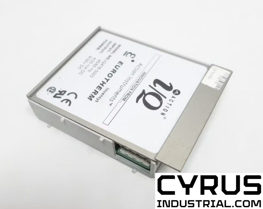
Description The Q478 is a DC powered DIN rail mount, frequency input signal conditioner with 1800VDC isolation between input, output and power. The field configurable input and output offers flexible, wide ranging capability for variable frequency drives, magnetic pickups, turbine flowmeters, and other pulse or frequency output transducers. The input of the Q478 can be configured for any frequency span from 2Hz to 10,000Hz. The input amplitude threshold sensitivity can be adjusted from 150mVp to 10Vp to ensure accurate frequency measurement and minimize transient noise related errors. The maximum input amplitude is 150 Vrms. The output can be set for either 0-5V, 0-10V, 0-1mA, 0-20mA or 4-20mA. The Q478 can be field configured for virtually any frequency input to DC signal output within the ranges specified. There is also an 8VDC excitation source common to the input. This can be used as a signal source for relay contacts or as an excitation source for open collector type proximity sensors. The Q478 is DC powered and will accept any power between 9 and 30VDC. TouchCAL Technology The Q478 utilizes TouchCAL Technology to greatly simplify con- figuration. The high and low input ranges are stored in non- volatile memory and correspond to the high and low output range which is selected via DIP switches. Diagnostic LEDS The Q478 utilizes three diagnostic LEDs. The green (RUN) LED indicates DC power and input signal status. Active line power is indicated by an illuminated LED. If the input signal is 7% or more high, the LED will flash at 8Hz. If the input signal is 7% or more low, the LED will flash at 4Hz. The yellow (IN) LED is lit when calibrating the input. The red (OUT) LED is lit when calibrating the output. Application The Q478 field configurable, frequency input signal conditioner is useful in eliminating ground loops and interfacing pulse output transducers, such as turbine flow meters and magnetic pickups, to data acquisition and control systems. | Advanced digital technology, combined with ASIC technology, provides a stable output at low frequencies for higher accuracy, and 3-way isolation which completely eliminates ground loops from any source. Configuration Any 2Hz range from 0 to 10,000Hz can be converted to a full scale output signal (e.g. 0-2Hz/4-20mA or 9998-10,000Hz/4-20mA). Unless otherwise specified, the factory presets the Model Q478 as follows:
Note that "Sensitivity" refers to the noise rejection level (the trigger threshold of the input). For other I/O ranges, refer to the tables. WARNING: Do not change switch settings with power applied. Severe damage will result! 1. With power off, snap off the faceplate by lifting the right edge away from the heatsink. Then slide the heatsink forward and off the module. The output switch block (SW2) is located under the heatsink. Choose the desired output voltage/current range from Table 1 and set positions 1-8 of SW2. 2. Set the input sensitivity switch (SW2, 9 & 10) to LO for input amplitudes between 150mVp and 50Vrms, with noise rejection to 1Vp; or to HI for input amplitudes between 500mVp and 150Vrms, with noise rejection up to 10Vp. 3. Return the heatsink to its original position and attach the faceplate before beginning calibration. |
Features
MANUFACTURERS


Price history
The price has not changed yet. We will show it on this chart once it changes